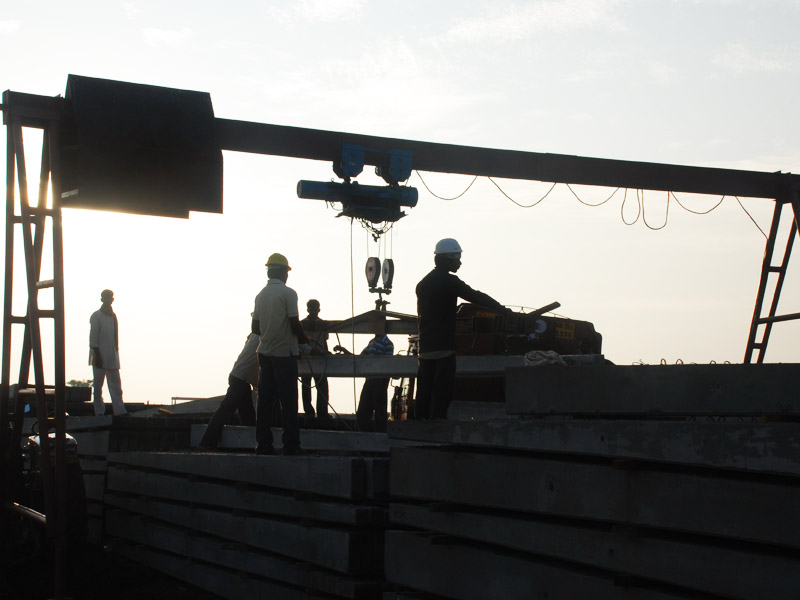
This post outlines recommended practices for the safe and efficient selection, handling, and erection of concrete poles for overhead power and telecommunication lines [ref. IS 7321 -1974]. Adherence to these guidelines ensures the structural integrity of the poles and the overall reliability of the overhead line system.
Selection of Concrete Poles:
- Concrete poles shall comply with the following Indian Standard specifications: IS: 785-1964 (Reinforced Concrete Poles), IS: 1678-1960 (Prestressed Concrete Poles), IS: 1332-1959 (Reinforced Concrete Lighting Columns), and IS: 2193-1963 (Prestressed Concrete Lighting Columns).
- Pole length selection should consider the line type (transmission or distribution), required conductor clearance from the ground, anticipated conductor sag, cross-arm placement, and planting depth. Refer to the relevant Indian Electricity Rules and associated amendments for specific guidance.
- The chosen poles must possess the necessary strength to withstand anticipated loads with an adequate safety factor, as outlined in the relevant Indian Standards.
- Dimensional tolerances, uprightness, provision of holes for fittings and lifting hooks, earthing arrangements, markings, and surface finish (free from cracks and with good quality) should all be verified to ensure pole compliance with relevant specifications.
- Poles should originate from lots that have undergone successful sample testing as per IS: 785-1964 and IS: 1678-1960.
Handling Practices for Concrete Poles:
- Due to their weight and lower impact resistance compared to metal poles, concrete poles require careful handling during transportation.
- The preferred handling orientation positions the major axis of the pole horizontally.
- A minimum of two lifting points must be employed, with one positioned approximately 1/5th of the length from the bottom and the other positioned roughly 1/4th of the length from the top. For poles exceeding 500 kg, utilize four designated lifting points.
- Single-point lifting is strictly prohibited to prevent stress concentration and potential cracking.
- During manual handling, ensure uniform support along the entire pole length, as opposed to supporting only the ends.
Loading, Unloading, and Transportation Procedures:
- Whenever feasible, utilize cranes or similar mechanical equipment for loading and unloading poles. If necessary, manual methods can be implemented, following these steps:
- Construct an inclined slide using wooden sleepers or steel rails to facilitate loading poles onto the vehicle.
- Employ ropes to carefully drag poles onto the slide.
- Meticulously position poles to avoid any contact or impact between them.
- Implement similar procedures for unloading, incorporating cushioning materials like sandbags at the ground level.
- Refrain from dropping, jerking, or striking poles during handling activities.
- Stack poles within the vehicle, separating each layer with wooden battens to ensure even support.
- During transportation on trucks or trailers, position poles parallel to the direction of travel with the major axis horizontal. Secure the poles firmly to the vehicle.
- For poles exceeding the truck bed length, create a balanced overhang at both ends and bind multiple poles together for enhanced stability.
- As an alternative, transport poles with the minor axis vertical (flat position) if the vehicle can fully accommodate them within its body. In this scenario, increase cushioning material and utilize more separate battens between layers.
- For bullock cart transportation, suspend poles from multiple points to prevent ground contact during the journey. Alternatively, stack poles on the cart body or utilize wheeled support structures.
Concrete Pole Erection Practices:
- Align the major axis of the erected pole with the direction of the overhead power line.
- Exercise caution to prevent jerking, swinging, or striking poles during the lifting process.
- Maintain the designed spacing between poles to ensure proper load distribution on the line.
- Bury the poles to a minimum depth as specified in the relevant Indian Standards, utilizing appropriate equipment such as earth augers to excavate the foundation pit.
- Larger concrete poles may not necessitate a foundation if the soil exhibits good bearing capacity.
- Implement concrete base plates for poles susceptible to wind, storms, soil erosion, or poor soil conditions. Timber baulks may be used with prior approval from the engineer-in-charge.
- In loose soil environments, construct a concrete base extending 150 mm above the planting depth to prevent overturning.
- Refer to IS: 5613 (Part I/Section 2)-1971 for detailed instructions on foundation preparation and erection procedures. Direct pole erection methods are commonly employed. Utilize tractor-trailers if available to facilitate the process.
- Provide temporary support stays before applying tension to the conductors.
- Prepare, cast, and cure concrete base blocks and foundation concrete as per IS: 456-19
| Also Read: ISI-CERTIFIED PSCC POLES ARE THE CORNERSTONE OF UNWAVERING POWER DISTRIBUTION EXCELLENCE
✍Research and Written by Bheemesh Kacharagadla

